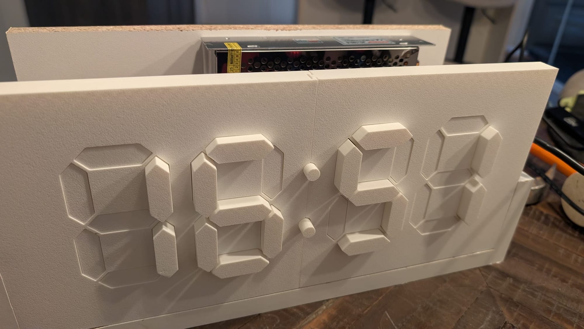
Kinetic Clock
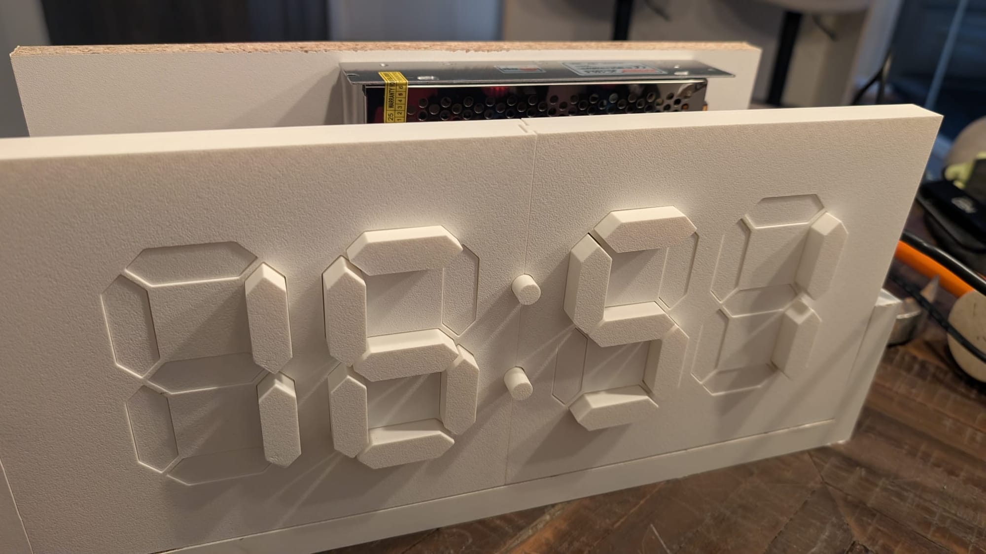
There’s something mesmerizing about motion-based clocks — where time is displayed not just as numbers, but as movement.
This is my take on a Kinetic Digital Clock — an Arduino-driven, 3D-printed build that uses mechanical motion to form digital digits.
Concept
Instead of showing time on a screen, this clock physically moves flaps to form the digits.
Each segment of the 7-segment display is a 3D-printed arm, driven by a small servo motor.
The result is a clock that feels alive — every minute it animates, morphing smoothly from one number to the next.
The idea came from wanting something that blends electronics, motion, and 3D printing — something more dynamic than an LED display.
Components
Each number (0–9) is made up of seven segments, just like a regular digital clock.
Every segment is a mechanical “bar” that pivots up or down using a micro servo.
The Arduino controls these servos using simple timing logic, updating the pattern every minute.
| Component | Example | Amazon | AliExpress |
|---|---|---|---|
| Controller | Arduino Mega | https://amzn.to/4nEtkK8 | https://s.click.aliexpress.com/e/_c3mVtKft |
| Motor shield | Arduino Mega Sensor Shield | https://amzn.to/4oZwnOq | https://s.click.aliexpress.com/e/_c3gWBKb1 |
| 30 servo motors | SG90 | https://amzn.to/43QqA5p | https://s.click.aliexpress.com/e/_c3D5lkTv |
| RTC | DS3231 | https://amzn.to/43gtbp1 | https://s.click.aliexpress.com/e/_c3mv2RUJ |
| Power supply | 5v/20A | https://amzn.to/3LnwlkM | https://s.click.aliexpress.com/e/_c3xSP0rh |
| Battery | CR2032 | https://amzn.to/47q8zx5 | https://s.click.aliexpress.com/e/_c39QeH3l |
| 3D filament | any type |
3D Printing
The design is forked from
 Instructables
and the box around the clock was made from scrap wood 18mm pieces i had laying around.
Print settings:
- 0.2 mm layer height
- 15–20% infill
- No supports needed
Electronics
Servos connect to the Arduino Mega Sensor Shield through PWM pins
A DS3231 module keeps accurate time, even when power is disconnected.
Each servo receives:
- Signal → Arduino PWM pin
- Power → 5 V regulator
- Ground → common GND
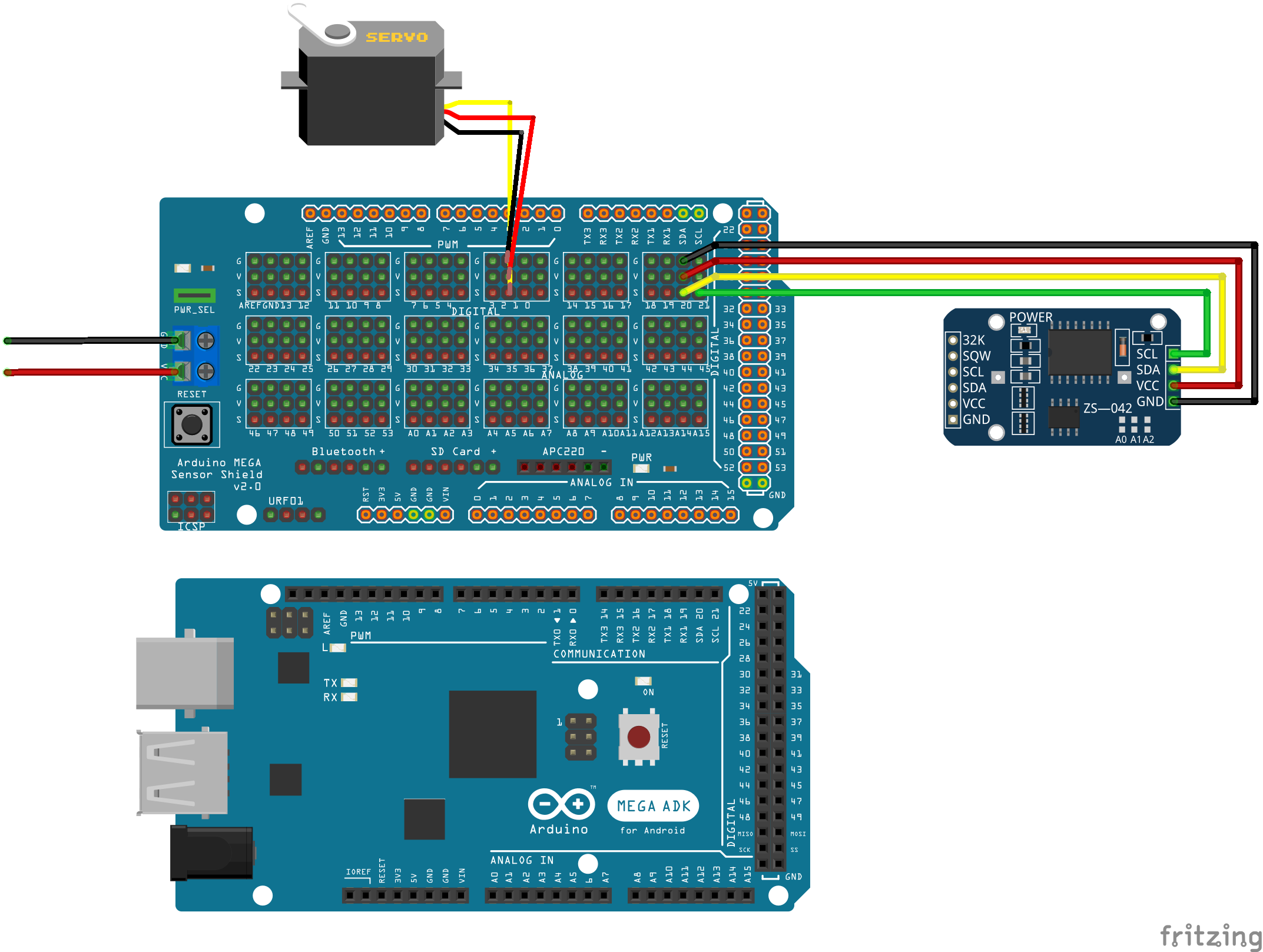
Eventually all motors should be connected to the 30 pins in this fashion
Assembly
Once printed, assembly is quite straightforward
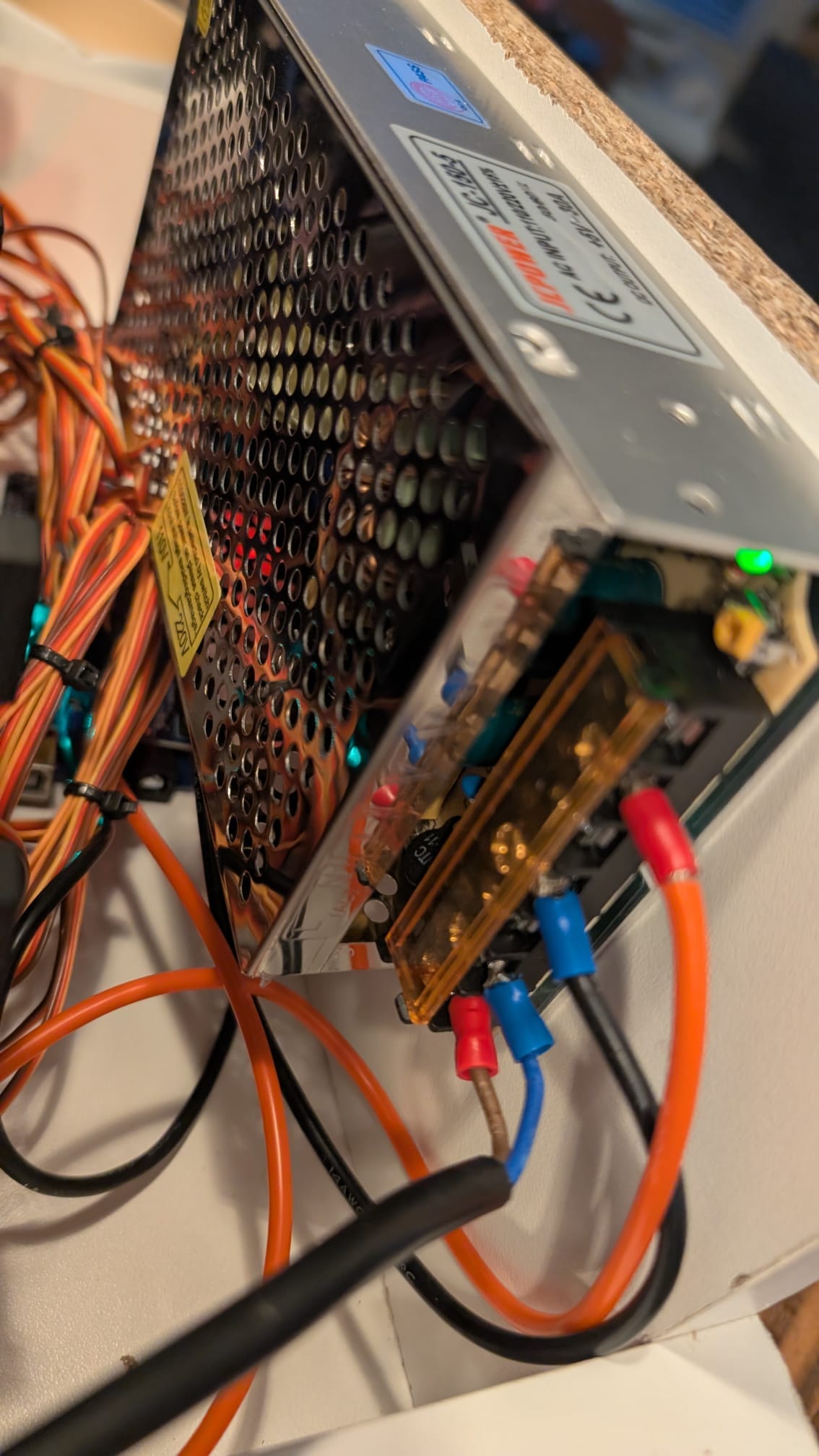
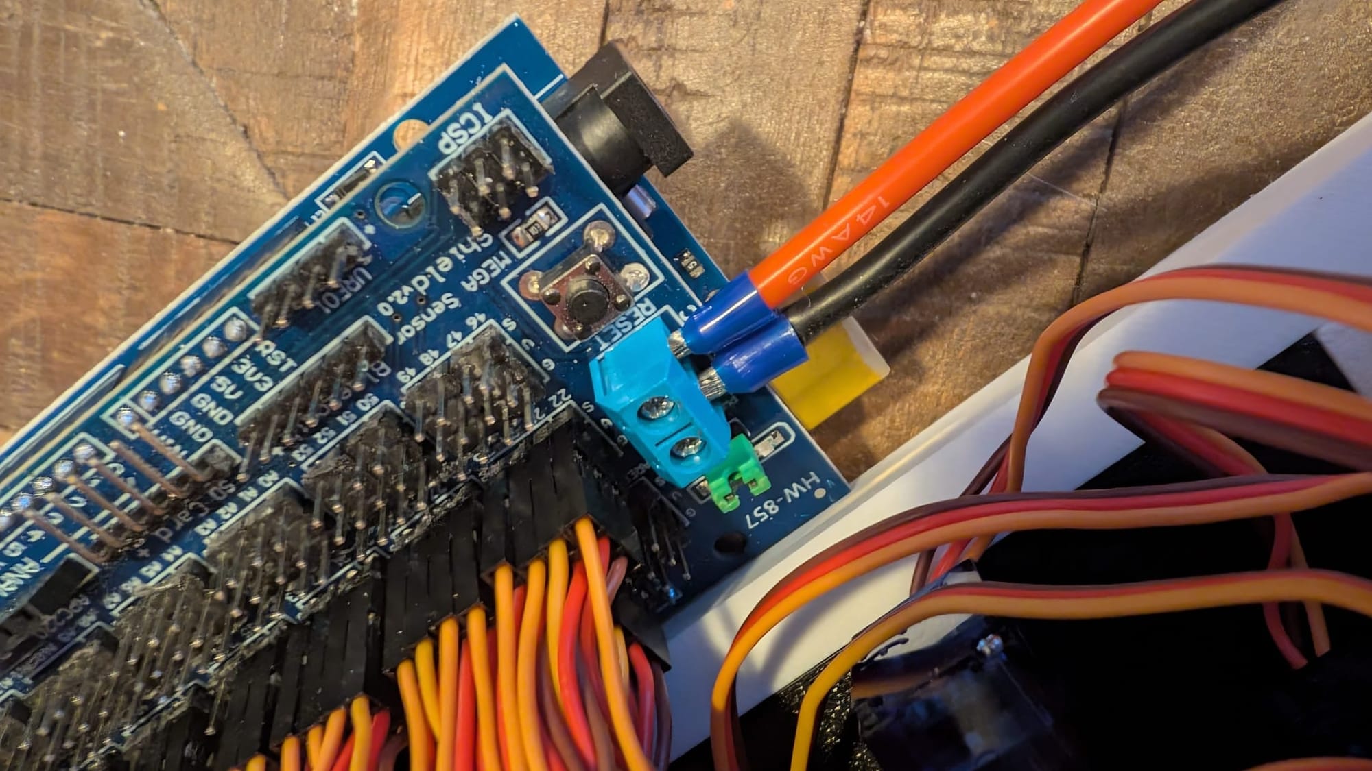
If you plan to power Arduino+Shield+Motors from a single external power supply, you should keep the VCC-PWR jumper on the Shield (usually green jumper), but in that case, DO NOT connect the USB to the Arduino, in that case you might back-feed power back to your USB port.
If you plan to power only the Shield+Motor from external supply, and the Arduino from a USB - so make sure to REMOVE the VCC-PWR jumper.
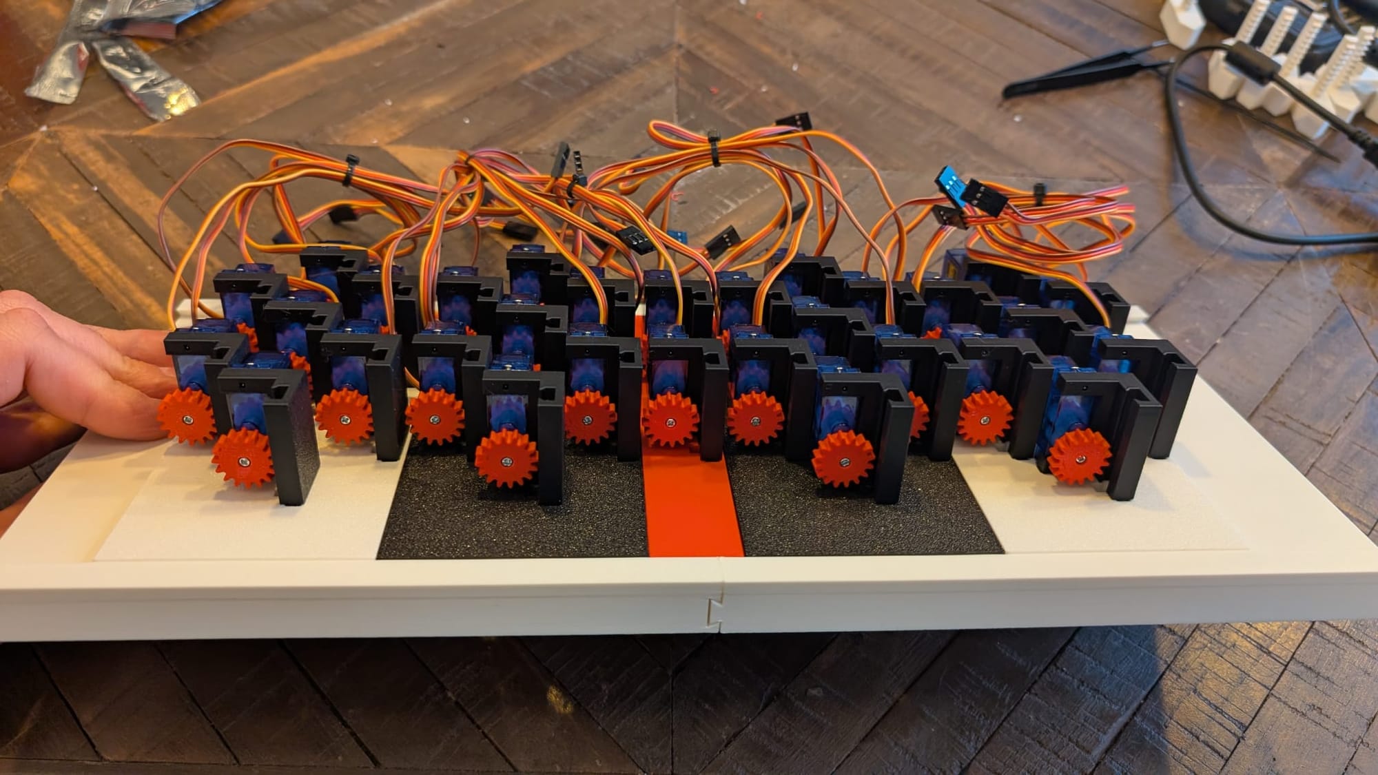
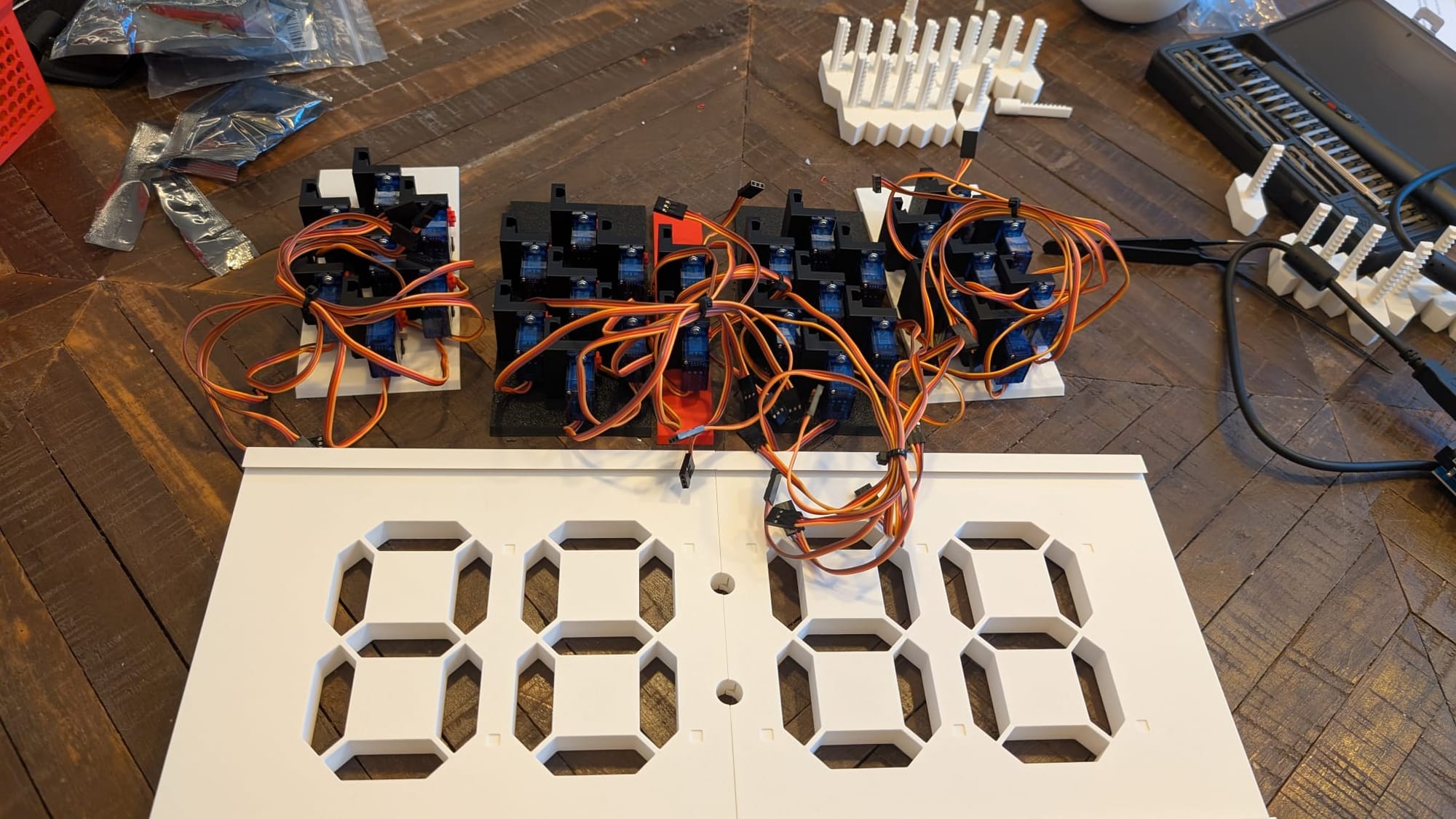
- Mount the servos each of the back panels
- Connect the power supply to the Arduino board
Calibration
- Connect wires to the Arduino and RTC based on the diagram above
The motors pins are connecting to the following pins on the shield
{2, 3, 4, 5, 6, 7, 8}, // 1st digit
{9, 10, 11, 12, 13, 14, 15}, // 2nd digit
{22, 23, 24, 25, 26, 27, 28}, // 3rd digit
{29, 30, 31, 32, 33, 34, 35} // 4th digit - Calibrate the motors (if needed), then upload the logic sketch.
- Power it up — and watch time come alive!
Calibrate motors
If needed - you can calibrate the motors by uploading this sketch, then on serial monitor, each the needed motors to 0 degrees, insert the segment, then move the motor to 180 degrees (if your motors are 0-360, adjust accordingly)
#include <Servo.h>

#define NUM_SERVOS 30

// Store servo instances and pin mapping
Servo servos[NUM_SERVOS];
int servoPins[NUM_SERVOS] = {
  2, 3, 4, 5, 6, 7, 8,
  9, 10, 11, 12, 13, 14, 15,
  22, 23, 24, 25, 26, 27, 28,
  29, 30, 31, 32, 33, 34, 35,
  38, 39
};

void setup() {
  Serial.begin(9600);
  Serial.println("=== Servo Control Mode ===");
  Serial.println("Type: PIN DEGREE (example: 23 180)");
  Serial.println("Moves the servo on that pin to the given degree.");
  Serial.println();
}

void loop() {
  if (Serial.available()) {
    int pin = Serial.parseInt();     // Read the first integer (servo pin)
    int degree = Serial.parseInt();  // Read the second integer (angle)

    if (pin > 0 && degree >= 0 && degree <= 180) {
      int servoIndex = findServoIndex(pin);

      if (servoIndex >= 0) {
        Serial.print("Moving servo on pin ");
        Serial.print(pin);
        Serial.print(" to ");
        Serial.print(degree);
        Serial.println(" degrees...");

        // Create a temporary servo just for this action
        Servo tempServo;
        tempServo.attach(pin);
        delay(100);
        tempServo.write(degree);
        delay(800); // give servo time to move
        tempServo.detach();

        Serial.println("Done. Servo detached.");
      } else {
        Serial.println("Pin not found in servo list.");
      }
    } else {
      Serial.println("Invalid input. Use format: PIN DEGREE (e.g. 23 90)");
    }

    // Clear serial buffer
    while (Serial.available()) Serial.read();
  }
}

// Find servo index from pin number
int findServoIndex(int pin) {
  for (int i = 0; i < NUM_SERVOS; i++) {
    if (servoPins[i] == pin) return i;
  }
  return -1;
}
Coding
This code differs from the original one by using the newer `RTClib` library (by Adafruit), as well as adding a smooth motion between the transitions.
#include <Wire.h>
#include "RTClib.h"
#include <Servo.h>
RTC_DS3231 rtc;
// --- CONFIGURATION ---
const int DIGIT_PINS[4][7] = {
{2, 3, 4, 5, 6, 7, 8}, // 1st digit
{9, 10, 11, 12, 13, 14, 15}, // 2nd digit
{22, 23, 24, 25, 26, 27, 28}, // 3rd digit
{29, 30, 31, 32, 33, 34, 35} // 4th digit
};
const int COLON_PINS[2] = {38, 39};
// Segment ON/OFF mapping (1 = ON, 0 = OFF)
const int DIGIT_TO_SEGMENT_MAPPING[10][7] = {
{1, 1, 1, 1, 1, 1, 0}, // 0
{0, 1, 1, 0, 0, 0, 0}, // 1
{1, 1, 0, 1, 1, 0, 1}, // 2
{1, 1, 1, 1, 0, 0, 1}, // 3
{0, 1, 1, 0, 0, 1, 1}, // 4
{1, 0, 1, 1, 0, 1, 1}, // 5
{1, 0, 1, 1, 1, 1, 1}, // 6
{1, 1, 1, 0, 0, 0, 0}, // 7
{1, 1, 1, 1, 1, 1, 1}, // 8
{1, 1, 1, 1, 0, 1, 1} // 9
};
// Motion settings
const int SEGMENT_ON_POS = 90; // Segment lit
const int SEGMENT_OFF_POS = 180; // Segment off
const int STEP_DELAY = 10; // milliseconds per smooth step
const int STEP_SIZE = 1; // degrees per step
Servo digitServos[4][7];
Servo colonServos[2];
int currentAngles[4][7]; // to track smooth motion
// --- FUNCTIONS ---
void smoothMove(Servo &servo, int ¤tPos, int targetPos) {
if (currentPos == targetPos) return;
int step = (currentPos < targetPos) ? STEP_SIZE : -STEP_SIZE;
currentPos += step;
servo.write(currentPos);
}
// --- SETUP ---
void setup() {
Serial.begin(115200);
Wire.begin();
if (!rtc.begin()) {
Serial.println("Couldn't find RTC!");
while (1);
}
if (rtc.lostPower()) {
Serial.println("RTC lost power, setting time from compile time...");
rtc.adjust(DateTime(F(__DATE__), F(__TIME__)));
}
// Attach digit servos
for (int d = 0; d < 4; d++) {
for (int s = 0; s < 7; s++) {
digitServos[d][s].attach(DIGIT_PINS[d][s]);
digitServos[d][s].write(SEGMENT_OFF_POS);
currentAngles[d][s] = SEGMENT_OFF_POS;
}
}
// Attach colon servos (always ON)
for (int i = 0; i < 2; i++) {
colonServos[i].attach(COLON_PINS[i]);
colonServos[i].write(90); // Always ON
}
Serial.println("Clock initialized. All segments OFF, colons ON at 90°.");
}
// --- LOOP ---
void loop() {
static unsigned long lastUpdate = 0;
static int lastDigits[4] = {-1, -1, -1, -1};
DateTime now = rtc.now();
int hour = now.hour();
int minute = now.minute();
int digits[4] = {
hour / 10,
hour % 10,
minute / 10,
minute % 10
};
// Only update when time changes
if (millis() - lastUpdate >= 1000) {
lastUpdate = millis();
Serial.print("Time: ");
Serial.print(hour);
Serial.print(":");
Serial.println(minute);
}
// Smoothly move servos toward their target angles
for (int d = 0; d < 4; d++) {
int num = digits[d];
for (int s = 0; s < 7; s++) {
int targetAngle = (DIGIT_TO_SEGMENT_MAPPING[num][s] == 1)
? SEGMENT_ON_POS
: SEGMENT_OFF_POS;
smoothMove(digitServos[d][s], currentAngles[d][s], targetAngle);
}
}
delay(STEP_DELAY);
}
Video
Conclusion
- I'd like to add an ESP32 module maybe (to make it network time sync)
- Power supply stability is key, ensure you have at least of 20A in your power supply, otherwise your motor would jitter.
- Cable management make all the servo wires easier to manage
- Servo motors can be noisy, it is better to check the dB (if specified) to make sure they are quite (nobody likes a noisy clock)
If you connect an external power supply to power both Arduino/Shield + Motors -> make sure to remove the VCC-PWR jumper from the Shield (green pin), otherwise you could backtrack power back to your PC USB port (which could lead to bad news)